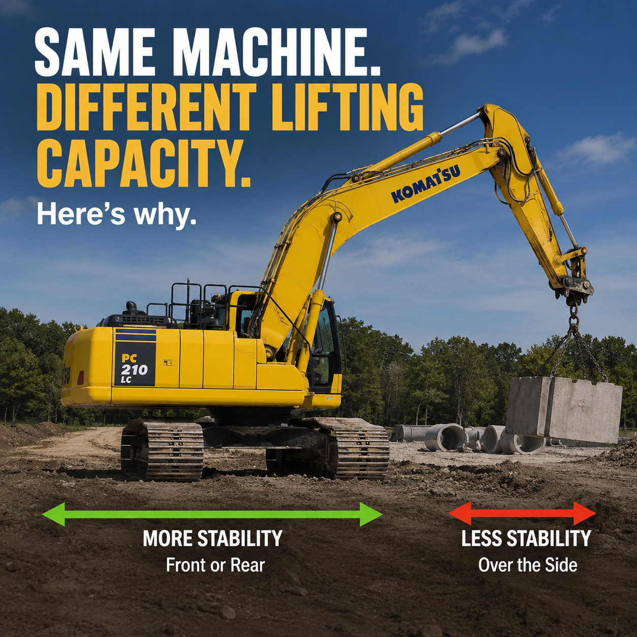
Why Can an Excavator Lift More Over One Part of Its Tracks Than Another?
At first glance, an excavator looks like it should be equally strong in every direction. The upper structure rotates 360 degrees, the tracks appear roughly symmetrical, and the boom can swing from one side of the machine to the other without changing anything about the hydraulic system.
But put a heavy load on the hook and the story changes.
An excavator's lifting capacity can vary considerably depending on whether the boom is positioned over the front or rear of the tracks or over the side. The hydraulics haven't suddenly become weaker. What changes is the machine's stability.
Understanding why means looking at something operators deal with constantly, even if they don't describe it mathematically: the machine's tipping line.
Hydraulic Strength Isn't Always the Limit
When an excavator lifts something, there are two basic limits to how much it can handle.
One is hydraulic capacity. Eventually, the hydraulic system reaches the pressure at which it can no longer produce enough force to raise the load.
The other is stability. Long before the hydraulics run out of muscle, the load may create enough overturning force to begin tipping the machine.
Depending on boom position, reach, attachment configuration and machine setup, either one can become the limiting factor.
That's why asking, "How much can this excavator lift?" doesn't really have a single answer.
Think of the Tracks as the Machine's Footprint
Imagine looking straight down at an excavator.
The tracks form a long rectangular support area beneath the machine. As long as the machine's combined center of gravity remains within the effective support area, it stays stable.
But the dimensions of that footprint aren't equal.
The tracks are much longer than the machine is wide.
When the boom is positioned over the front or rear, the machine has the length of its undercarriage helping resist the overturning moment. When the boom is positioned over the side, the available distance to the tipping line is much shorter.
That difference can dramatically change lifting capacity.
The Tipping Line Is What Matters
The easiest way to understand this is to imagine an invisible line around which the excavator could begin to rotate.
When lifting over the side, that tipping line is generally associated with the outer edge of the track on the loaded side.
The horizontal distance between the machine's center of gravity and that line provides leverage resisting the load.
Now rotate the upper structure so the boom is positioned along the length of the tracks.
The relevant tipping geometry changes, and the machine generally has a larger effective support dimension available to resist overturning.
In simple terms:
A wider stability base in the direction of the load means greater resistance to tipping.
The excavator may have exactly the same engine, hydraulic pressure, boom cylinders and counterweight, but its ability to safely use that lifting force changes with orientation.
The Counterweight Is Part of the Equation
That large mass hanging off the back of an excavator isn't there just to make the machine look balanced.
The counterweight creates a resisting moment against the load carried by the boom.
Think of the excavator as a giant lever.
The load is trying to rotate the machine toward the bucket. The counterweight and the rest of the machine's mass are trying to keep it planted.
As the load moves farther away from the excavator, its leverage increases. That's why lifting capacity generally decreases as working radius increases.
A relatively modest load held far from the machine can create a larger overturning moment than a much heavier load carried close in.
Reach Can Matter as Much as Weight
Suppose an excavator can comfortably handle a particular object close to the tracks.
The operator begins extending the stick.
Nothing about the object changes. It weighs exactly the same.
But every foot of additional horizontal reach increases the leverage that load has against the machine.
A simplified way to think about the overturning effect is:
Load × horizontal distance = overturning moment
A 5,000-pound load at a 10-foot radius produces roughly the same basic load moment as a 2,500-pound load at a 20-foot radius.
Real excavator lift calculations are considerably more complicated, but the principle explains why radius is so important on a lift chart.
Boom Position Isn't the Only Variable
Orientation is only one reason an excavator's lifting capacity changes.
Boom height matters. Working radius matters. Attachment weight matters. Counterweight configuration matters. Track configuration can matter.
Even the bucket, coupler and lifting hardware consume some of the machine's available lifting capacity.
Ground conditions matter too.
A lift chart assumes specific machine configurations and conditions. Real ground may be sloped, soft, uneven or poorly compacted. If one track settles during a lift, the geometry that was keeping the machine stable can change very quickly.
That's one reason a machine that feels completely planted at the beginning of a lift can become much less comfortable as the load moves outward or sideways.
Why Doesn't the Manufacturer Just Make It Wider?
There is an obvious solution to side stability: make the undercarriage extremely wide.
That creates other problems.
An excavator still has to be transported, maneuver through jobsites, work beside structures and sometimes fit within road-transport restrictions. A wider undercarriage also adds weight and cost.
Some machines solve part of this problem with variable-width or hydraulically extending undercarriages. Certain specialized excavators can widen their stance for work and retract it for transportation or tight spaces.
But conventional excavators are ultimately a compromise between stability, mobility, weight and transportability.
Why Lift Charts Have So Many Numbers
This is also why excavator lift charts can initially look unnecessarily complicated.
They may provide different capacities for:
• lifting over the front or rear versus over the side,
• different working radii,
• different lift-point heights,
• different boom or arm configurations,
• and sometimes different track or blade positions.
Those numbers aren't simply estimates of how powerful the hydraulic cylinders are.
They describe how the entire machine behaves as a lifting system.
In some positions, hydraulic capacity may be the restriction. In others, stability may become the restriction first.
A 360-Degree Machine Isn't a 360-Degree Crane
One of the most interesting things about an excavator is that its rotating upper structure can make it appear mechanically identical in every direction.
It isn't.
The boom can rotate through a full circle, but the support structure beneath it doesn't rotate with it. The rectangular track footprint stays exactly where it is.
So every time the house swings, the relationship between the load, the machine's center of gravity and its potential tipping line changes.
That's why an excavator that feels extremely stable with a load in one position can feel very different after swinging that same load 90 degrees.
The machine hasn't lost any hydraulic power.
The geometry changed.
And when you're lifting with an excavator, geometry can be every bit as important as horsepower and hydraulic pressure.
Always use the manufacturer's lift chart and operating instructions for the specific machine, configuration and lifting conditions. General stability principles aren't a substitute for the rated capacities of the equipment being operated.