How Do Engineers Keep Large Machine Frames From Cracking Around Welds?
Heavy equipment is built to withstand tremendous forces. Excavators lift and swing heavy loads, bulldozers push against resistant material, wheel loaders repeatedly fill and dump buckets, and haul trucks carry enormous payloads across uneven terrain.
Behind all that work is a steel structure that must absorb, distribute, and withstand forces thousands of times throughout the machine's working life.
But even the strongest steel frame can develop cracks, particularly around welded connections.
Why?
The answer involves more than the strength of the steel or the quality of the weld. Engineers must consider how forces travel through a structure, how repeated loading affects metal, and how the shape and placement of a weld can influence where cracks begin.
Designing a durable machine frame requires a combination of structural engineering, fatigue analysis, careful welding procedures, and testing.
Let's explore how engineers approach the challenge.
Why Do Cracks Often Develop Around Welds?
Welding allows manufacturers to join steel plates, beams, and structural components into large, complex assemblies.
Without welding, manufacturing many modern heavy equipment frames would be considerably more difficult.
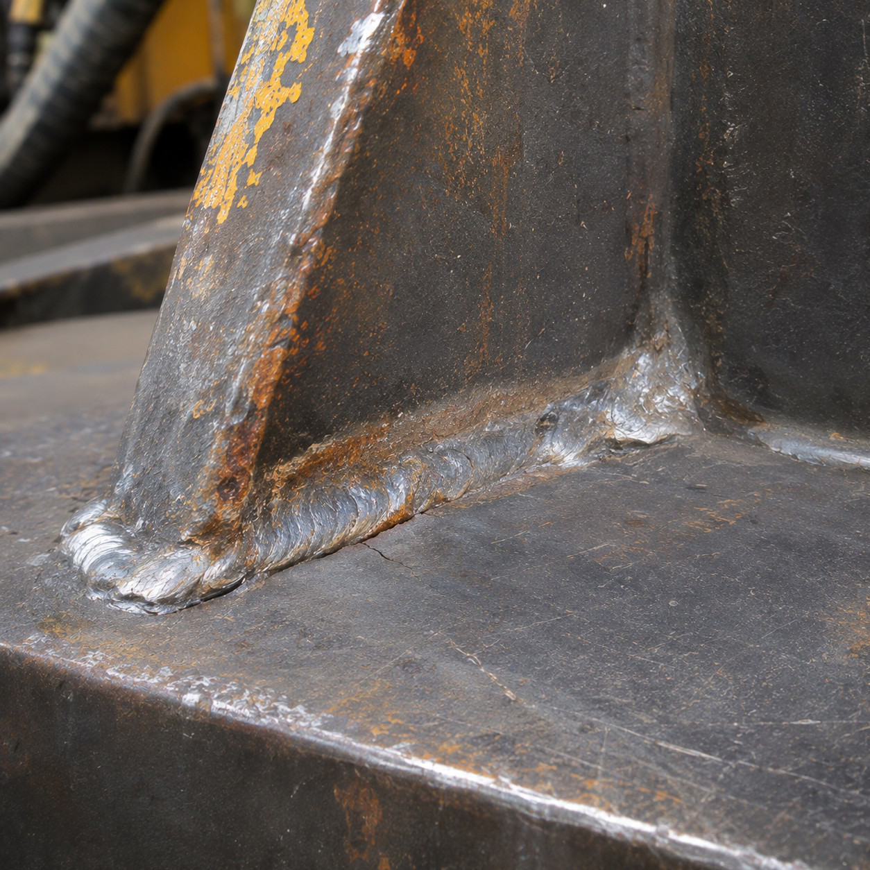
However, welded connections can also become locations where fatigue cracks develop.
Several factors contribute to this vulnerability.
Stress concentrations: Changes in geometry around a weld can cause stresses to become locally higher than those in the surrounding material.
Residual stresses: Heating and cooling during welding can leave internal stresses in the metal, even when the structure is not carrying an external load.
Weld imperfections: Certain defects, including lack of fusion, incomplete penetration, and cracks, can reduce fatigue resistance.
Repeated loading: Forces that repeatedly increase, decrease, or reverse can gradually initiate and propagate cracks.
Importantly, a properly executed weld is not necessarily weaker than the surrounding steel under a single static load. In some circumstances, the deposited weld metal may have higher tensile strength than the base material.
The challenge is that static strength and fatigue resistance are not the same thing.
A welded connection may be strong enough to support a substantial load once but still be vulnerable to damage when subjected to that load repeatedly.
What Is Metal Fatigue, and Why Does It Matter?
|
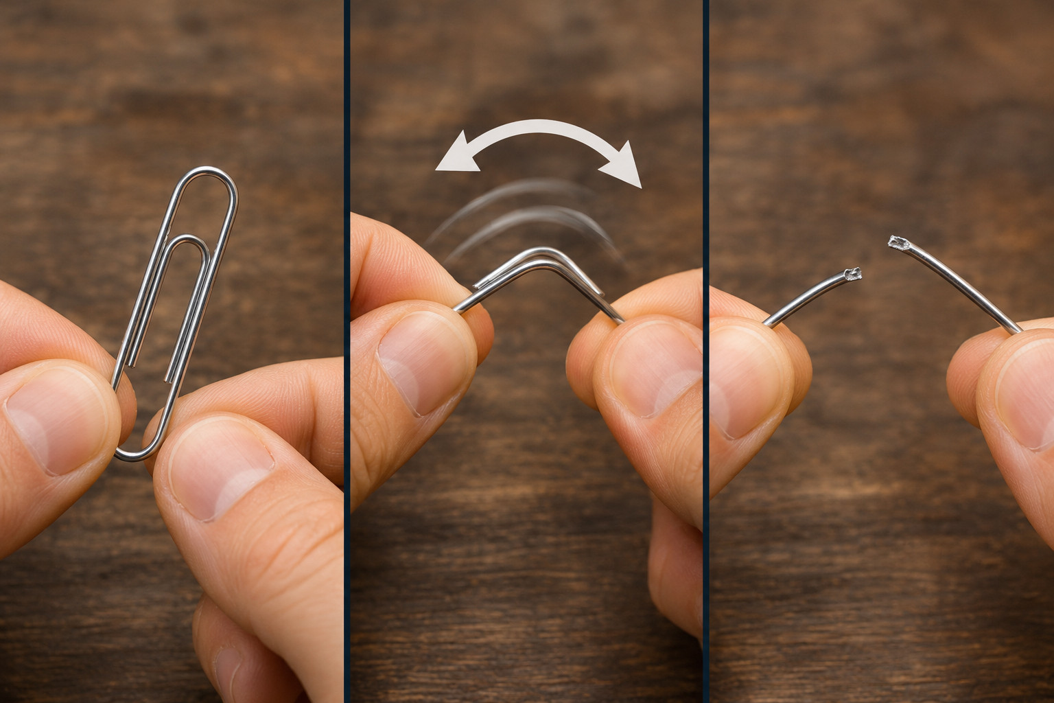
Imagine bending a paper clip back and forth. The metal may withstand the first few bends, but repeated bending eventually causes it to fracture. This is a simple illustration of metal fatigue. In heavy equipment, the process is usually less dramatic and takes place over many thousands or millions of loading cycles. Consider an excavator working throughout the day. Every time the operator digs, lifts, swings, or dumps material, forces travel through the boom, stick, upper structure, and supporting components. Those forces change as the machine moves. A particular welded connection might experience tension during one operation, compression during another, and varying combinations of bending and shear throughout the working cycle. Over time, these fluctuating stresses can cause microscopic fatigue cracks to initiate at vulnerable locations. Once a crack begins, repeated loading can cause it to grow incrementally. Eventually, the remaining uncracked material may no longer be capable of supporting the applied load, resulting in fracture. |
 |
Can a Frame Crack Even When the Machine Isn't Overloaded?
|
Yes. One of the most important characteristics of fatigue is that cracking can occur even when the maximum applied stress is below the material's yield strength. The frame does not have to bend permanently or experience a dramatic overload for fatigue damage to accumulate. This is why engineers cannot rely solely on calculations showing that a structure can support its maximum anticipated load. They must also evaluate how frequently the structure experiences different loads and how those loads change over time. For welded steel structures, fatigue performance is strongly influenced by the weld detail, local geometry, stress range, and number of cycles. |
 |
What Are Stress Concentrations?
|
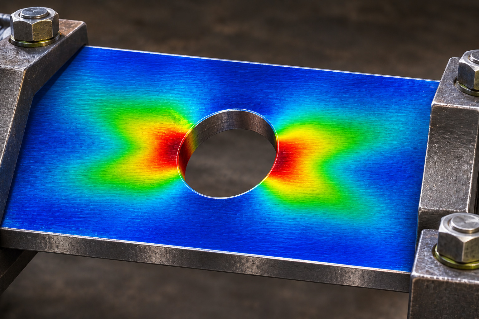
Stress is not always distributed evenly through a steel component. Consider a flat steel plate being pulled from opposite ends. If the plate has a consistent cross-section and is loaded uniformly, the stress distribution away from its ends may be relatively even. Now imagine drilling a hole through the middle of that plate. The load must travel around the opening, causing stress to become concentrated near portions of the hole's edge. A similar effect occurs around certain welded joints. Abrupt changes in thickness, sharp corners, attachment ends, and weld profiles can create localized increases in stress. These areas are known as stress concentrations. |
 |
Why Does Weld Shape Matter?
|
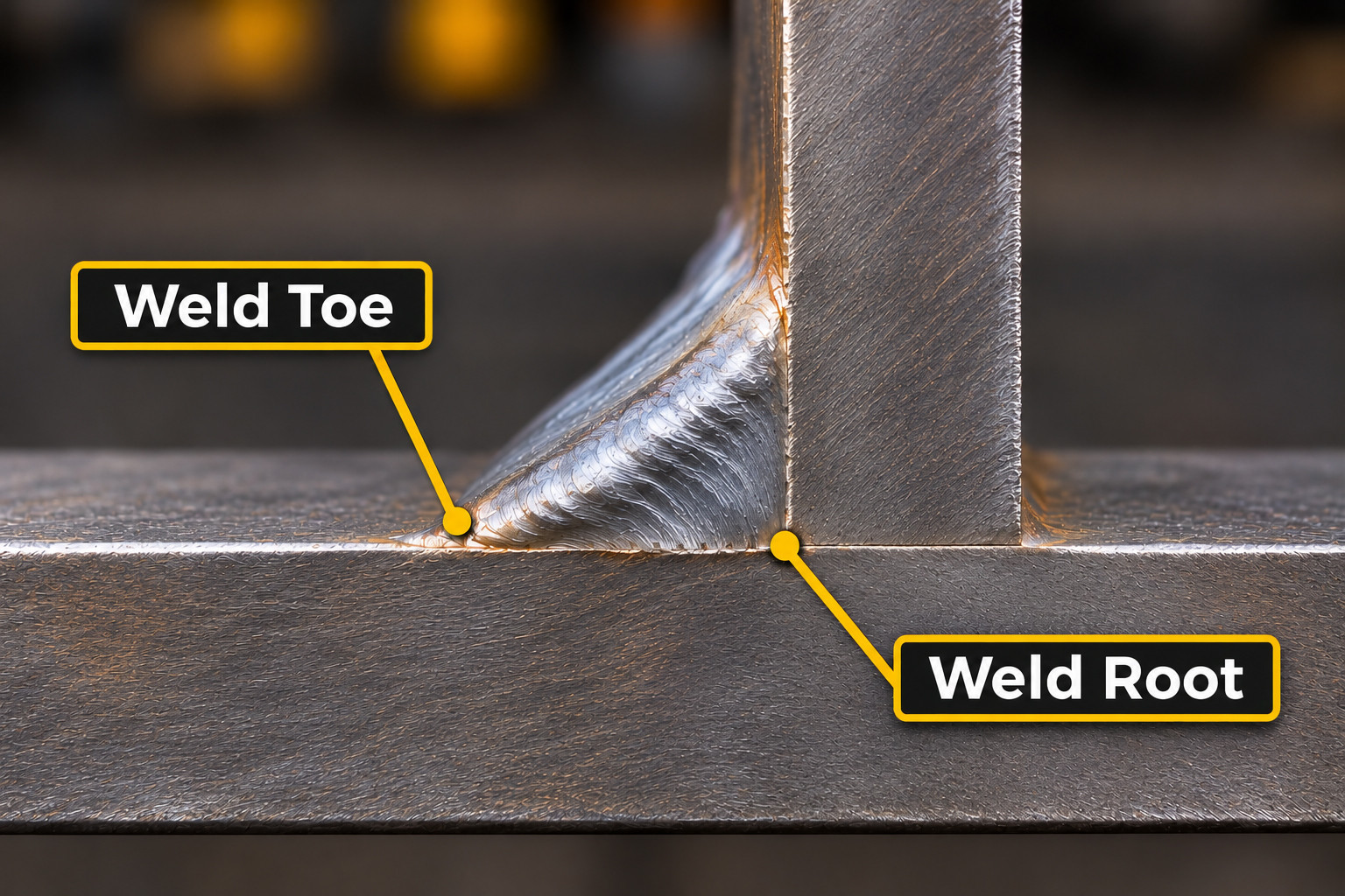
A weld has several important geometric features, including its toe and root. The weld toe is the location where the surface of the weld meets the base metal. The weld root is the deepest portion of the joint, opposite the weld face. Depending on the joint configuration, either location may become vulnerable to fatigue cracking. For example, an abrupt transition between the weld bead and the surrounding plate can create a stress concentration at the weld toe. If the connection experiences repeated loading, a fatigue crack may begin at that location. Engineers therefore pay close attention to joint geometry, weld size, weld profile, and the direction of applied forces. A smooth transition can improve fatigue performance in appropriate circumstances, but simply making a weld larger does not necessarily make the connection more fatigue-resistant. In fact, an unnecessarily large weld can increase welding distortion, residual stresses, material consumption, and manufacturing costs without addressing the underlying fatigue problem. The goal is not to produce the biggest weld possible. The goal is to create a joint that safely transfers the required loads without introducing unnecessary stress concentrations. |
 |
How Do Engineers Design Frames to Resist Fatigue Cracking?
Preventing fatigue problems begins long before the first weld is made.
Engineers must determine where forces will enter the structure, how those forces will be transferred between components, and which areas are likely to experience the greatest fluctuations in stress.
Several design strategies help improve durability.
|
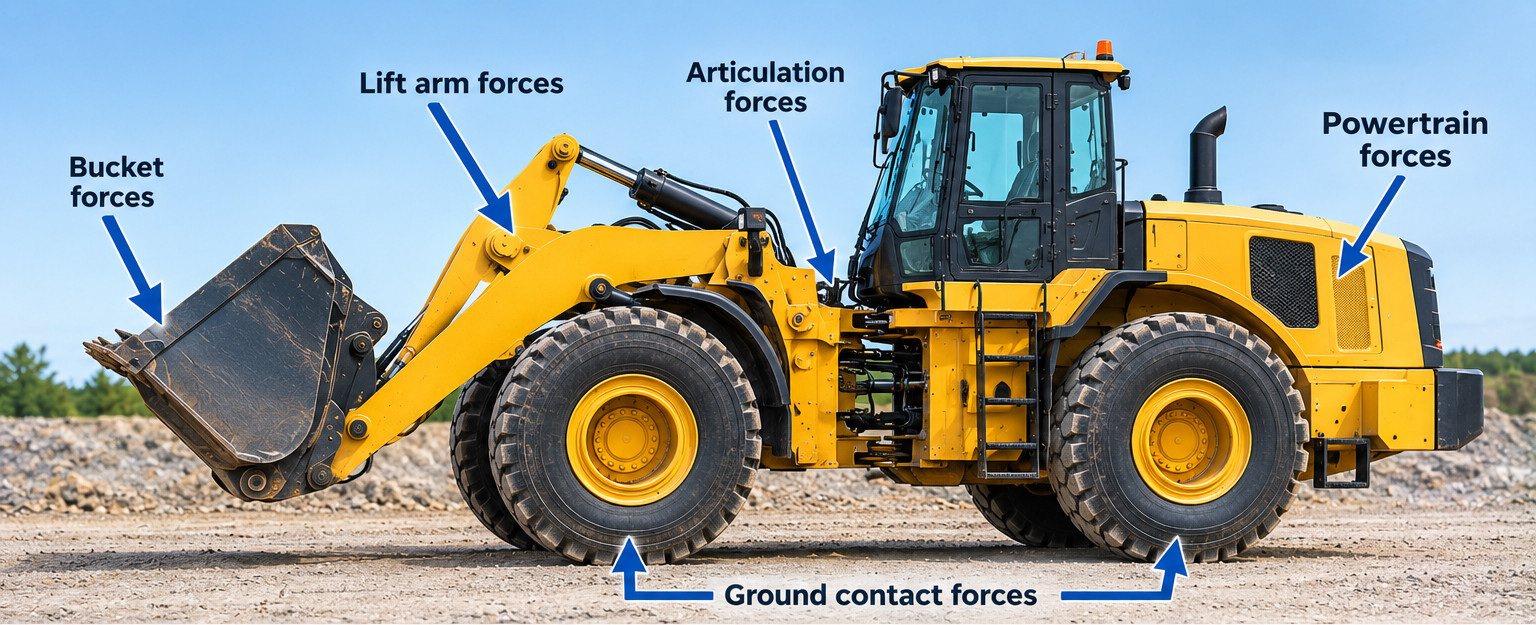
1. Distributing Loads Across the Structure Rather than allowing a large force to act through a small section of steel, engineers try to distribute that force through an appropriate load path. For example, the frame of a large wheel loader must withstand forces generated by the bucket, lift arms, articulation system, powertrain, and ground contact. If those forces are concentrated around a relatively small welded connection, that area may become vulnerable to fatigue. Engineers can modify the arrangement of structural members, plate thicknesses, and internal supports to distribute loads more effectively. The objective is to reduce damaging stress ranges without making the frame unnecessarily heavy. |
 |
|
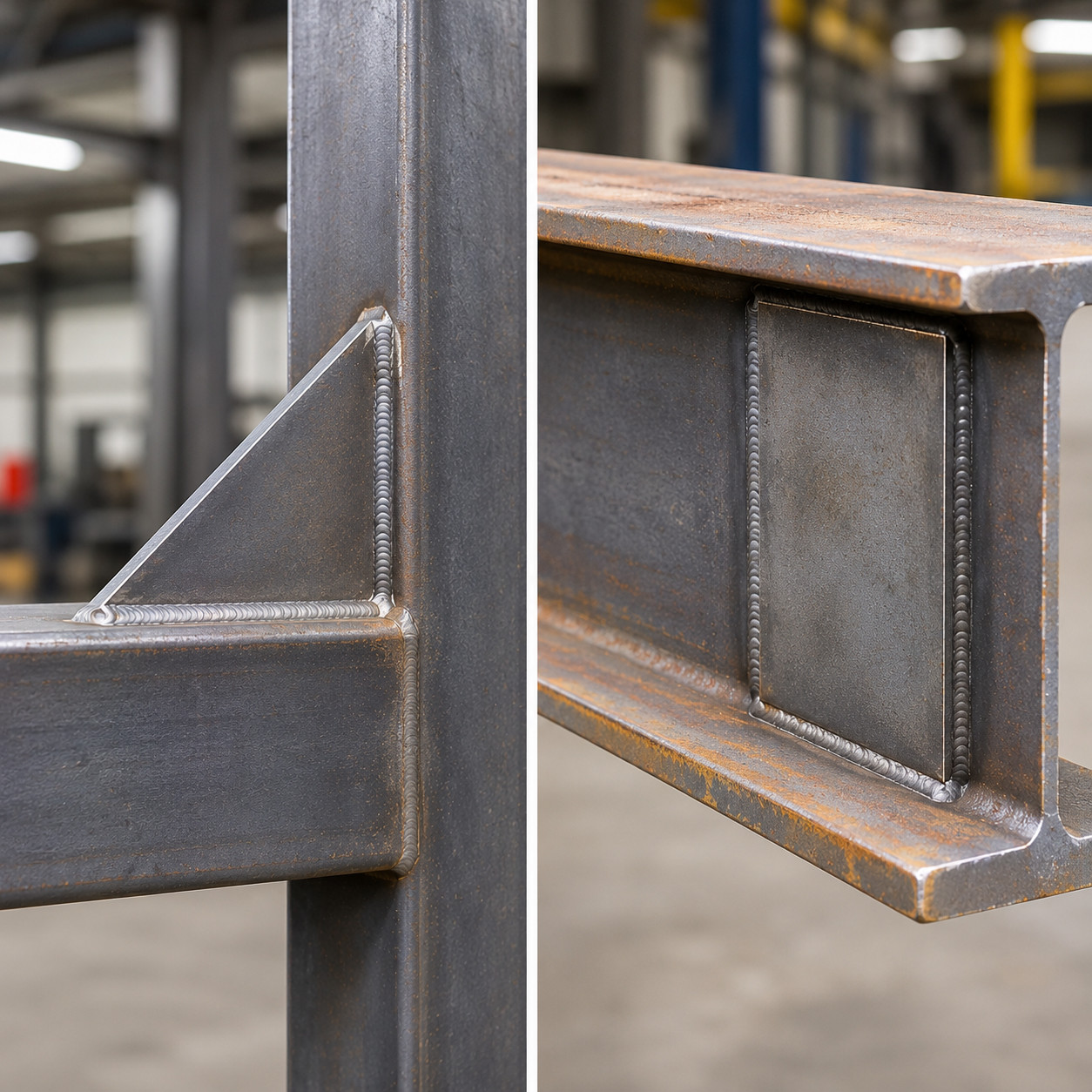
2. Using Gussets and Reinforcement Plates Gussets are reinforcing plates used to strengthen connections between structural members. They can help distribute forces, support joints, and reduce unwanted deformation. However, adding reinforcement is not automatically beneficial. A poorly designed gusset can create a new stress concentration at its end, particularly if it is welded onto a highly stressed section of plate. The reinforcement may make one area stiffer while transferring greater stress into an adjacent location. Engineers must therefore consider the shape, size, location, and attachment details of reinforcing plates. In some cases, a gradual transition or a different reinforcement arrangement provides better fatigue performance than simply adding more steel. |
 |
|
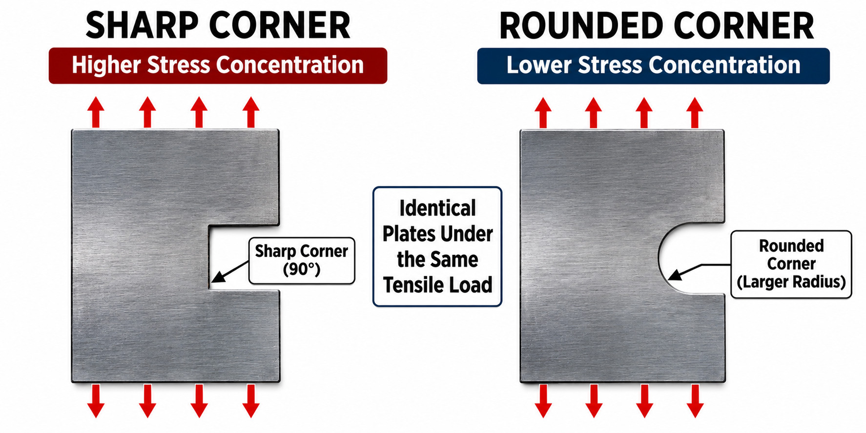
3. Avoiding Abrupt Changes in Geometry Sharp corners and sudden changes in section geometry can increase local stresses. Where practical, engineers use gradual transitions, suitable radii, and carefully designed connections. For example, transitioning between two different plate widths with a properly designed curved profile may reduce stress concentrations compared with an abrupt change. These details can have a substantial influence on fatigue life. |
 |
|
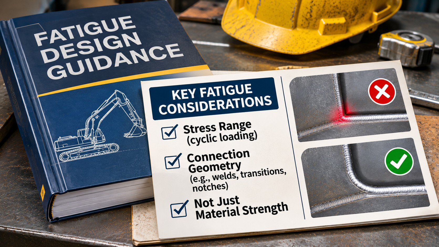
4. Positioning Welds Strategically Not every part of a machine frame experiences the same stress. Some regions carry relatively steady loads, while others experience significant fluctuations during operation. When practical, engineers position welded joints away from locations experiencing severe cyclic stresses. This can be particularly important near boom pivots, suspension mounting points, articulation joints, and other heavily loaded connections. Of course, welds cannot always be relocated. Structural requirements and manufacturing limitations often determine where connections must be placed. When a weld must be located in a highly stressed area, engineers may need to use a more fatigue-resistant joint detail or modify the surrounding structure. These principles are reflected in established fatigue design guidance, which emphasizes stress range and connection geometry rather than relying solely on material strength. |
 |
How Do Engineers Know Where a Frame Might Crack?
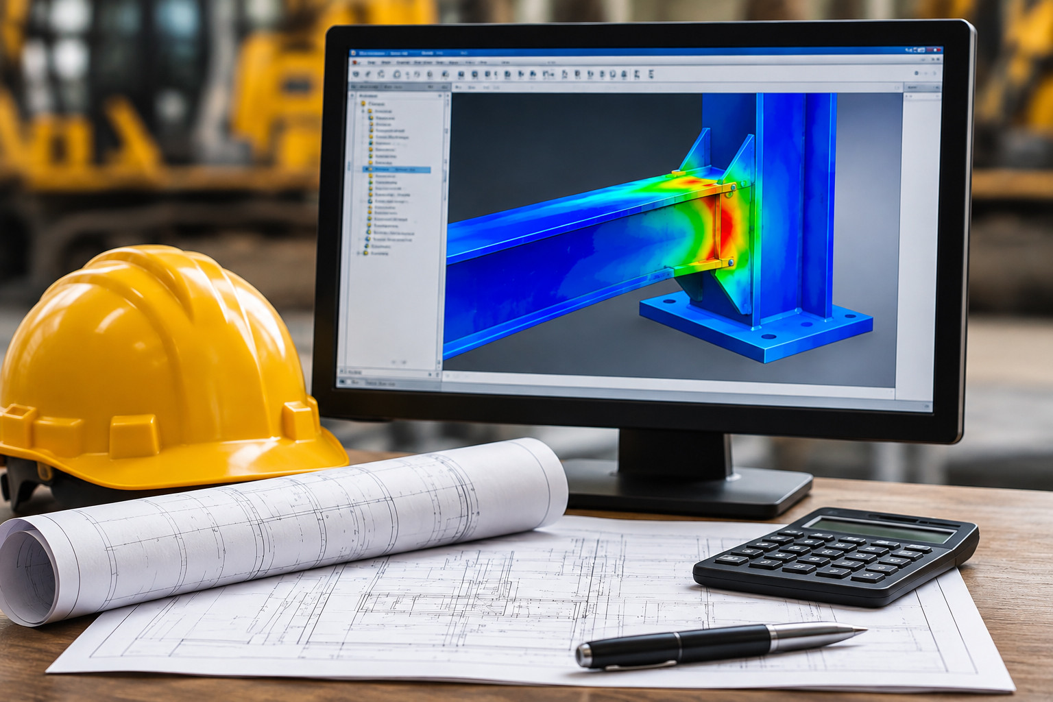
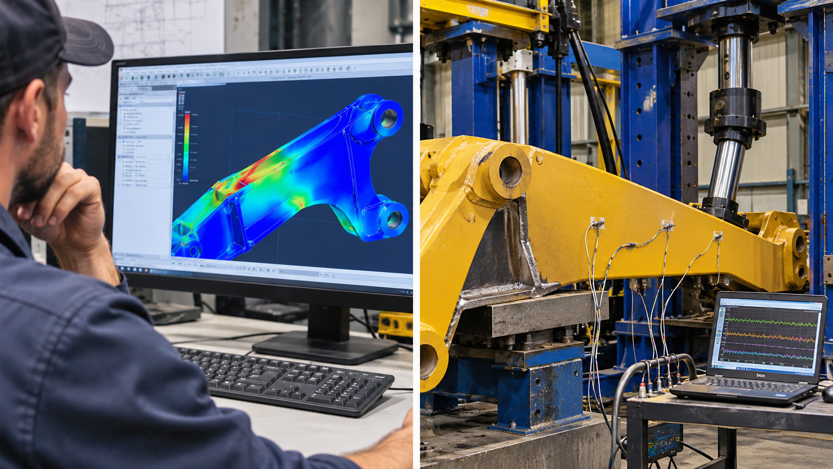
Modern engineering software allows designers to examine how a proposed structure responds to different loads before a physical machine is manufactured.
One of the most widely used methods is finite element analysis (FEA).
FEA divides a complex structure into many smaller elements. The software then calculates an approximate structural response based on the assigned material properties, geometry, connections, constraints, and applied loads.
For a heavy equipment frame, engineers may simulate operating conditions such as:
• An excavator digging into resistant material.
• A wheel loader lifting a full bucket.
• A haul truck travelling over uneven ground.
• A bulldozer pushing against a heavy load.
• A machine experiencing twisting forces as its wheels or tracks encounter different ground elevations.
The results help identify areas where stresses and deformation may become excessive.
Does FEA Show Exactly Where a Crack Will Form?
Not necessarily.
FEA is a powerful engineering tool, but its accuracy depends on the model and the assumptions used.
A model that represents a welded connection as a perfectly joined surface may not capture the local effects of the actual weld profile, root geometry, or imperfections.
Engineers may therefore use more detailed models or specialized fatigue assessment methods to evaluate critical welded joints.
They also need realistic information about the loads a machine will experience throughout its working life.
A machine operating on a smooth surface may experience a very different loading history from the same machine working over rough, uneven terrain.
FEA helps engineers identify potential weaknesses, but physical testing and field experience remain important.
Why Are Welding Procedures So Important?
Even a carefully designed frame can develop problems if the welding process is not properly controlled.
Welding involves intense localized heating followed by cooling.
This thermal cycle changes the material in and around the weld.
The region of base metal affected by welding heat, but not melted, is called the heat-affected zone (HAZ).
Depending on the steel composition and thermal cycle, this region may experience changes in hardness, toughness, strength, and microstructure.
Engineers and welding specialists must ensure that the welding procedure produces a connection with suitable mechanical properties and acceptable weld quality.
Controlling Preheat and Cooling Rates
Some steels require preheating before welding.
Preheating slows the cooling rate and can help reduce the risk of hydrogen-assisted cracking by allowing diffusible hydrogen more time to escape and reducing the formation of susceptible hard microstructures.
The required temperature depends on several factors, including:
• Steel composition and hardenability.
• Material thickness.
• Joint restraint.
• Welding process and consumables.
• Heat input and hydrogen levels.
Not every steel requires preheating, and excessive heat can create other metallurgical problems.
For this reason, welding temperatures should be established through appropriate procedures rather than guesswork.
Managing Heat Input
Heat input is influenced by welding current, voltage, travel speed, and process efficiency.
Too little or too much heat input can produce undesirable results, depending on the material and welding process.
For example, an unsuitable thermal cycle can affect the toughness or hardness of the heat-affected zone.
Engineers therefore establish acceptable welding parameters for the particular steel and joint.
Preventing Hydrogen Cracking
Hydrogen-assisted cracking is a separate concern from fatigue cracking.
It can occur during fabrication or after welding, sometimes before the machine has ever entered service.
The risk increases when diffusible hydrogen, susceptible microstructures, and tensile stresses occur together.
Preventive measures can include using appropriate low-hydrogen consumables, keeping materials clean and dry, controlling preheat and interpass temperatures, and following qualified welding procedures.
These practices are especially important when welding certain high-strength steels and thick, highly restrained structural components.
What Is a Welding Procedure Specification?
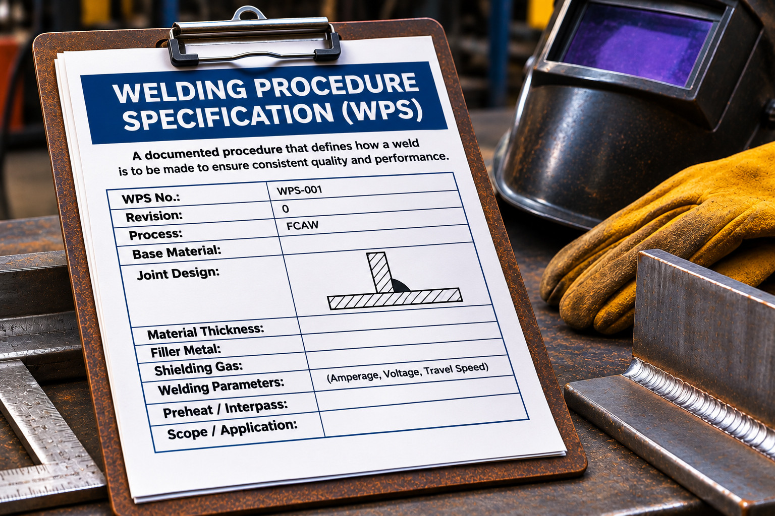
A Welding Procedure Specification, commonly called a WPS, provides instructions for producing a weld under defined conditions.
Depending on the application and governing standard, it may specify the welding process, base materials, filler metal, joint preparation, welding position, preheat and interpass temperatures, electrical parameters, and other essential requirements.
For critical structural applications, procedures may need to be qualified through testing or meet applicable prequalification requirements.
Welders may also need to demonstrate their ability to perform the required welds.
The purpose is consistency.
A manufacturer producing hundreds of machine frames needs confidence that welded connections will meet the specified requirements, regardless of which qualified welder performs the work.
A WPS does not eliminate fatigue risk on its own. The joint must also be properly designed for its service loads.
Can Special Weld Finishing Techniques Reduce Cracking?
Yes.
Certain post-weld improvement techniques can increase fatigue resistance, particularly where cracks would otherwise initiate at the weld toe.
Weld Toe Grinding
Carefully controlled grinding can improve the transition between the weld and base metal.
By reducing the severity of the weld toe geometry and removing certain shallow imperfections, the process can improve fatigue performance.
However, grinding must follow an appropriate procedure.
Excessive or incorrectly performed grinding can remove too much material or introduce new surface defects.
TIG Dressing
Tungsten inert gas (TIG) dressing involves remelting the weld toe to improve its profile.
When properly applied, it can reduce stress concentrations and improve fatigue resistance.
High-Frequency Mechanical Impact Treatment
|
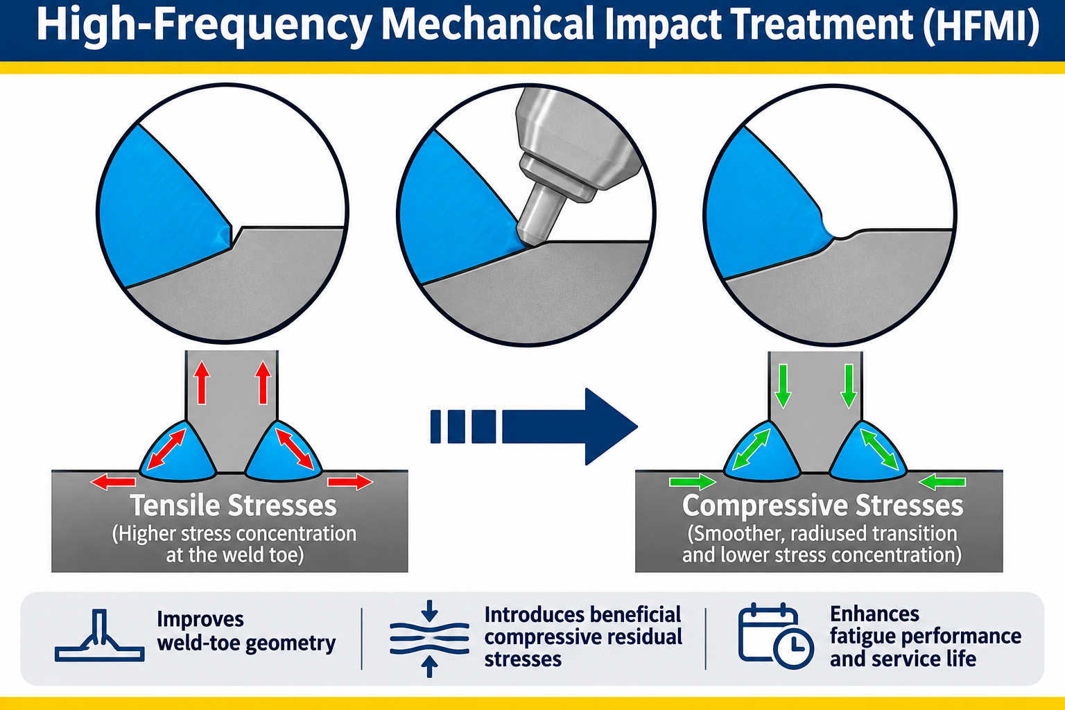
High-frequency mechanical impact (HFMI) treatment uses controlled mechanical impacts to modify the weld toe region. The treatment can improve the local profile and introduce beneficial compressive residual stresses. These compressive stresses can help resist the opening and growth of fatigue cracks under suitable loading conditions. However, improvement methods have limitations. A treatment that benefits a weld-toe-controlled joint may not solve a problem involving a crack at the weld root or an internal defect. The appropriate technique depends on the joint design, loading conditions, material, and applicable fatigue design requirements. |
 |
Does Using Thicker Steel Prevent Cracking?
It might seem logical that making a frame thicker would automatically make it more resistant to cracking.
But the relationship is more complicated.
Increasing plate thickness can reduce nominal stress under certain loading conditions. However, it can also increase machine weight, affect structural stiffness, and change how loads are distributed.
Thicker welded components can also present additional fabrication challenges, including greater restraint and more demanding welding requirements.
Furthermore, the fatigue strength of some welded details decreases with increasing material thickness, even when nominal stress is considered. This is known as the thickness effect.
Engineers must therefore evaluate the entire structure rather than assuming thicker steel is always the solution.
What About High-Strength Steel?
Higher-strength steel allows engineers to achieve greater load-carrying capacity with less material in some applications.
However, increasing the tensile strength of the steel does not necessarily produce a corresponding improvement in the fatigue resistance of an as-welded joint.
In many welded structures, fatigue performance is governed primarily by the joint geometry and applied stress range.
This is why engineers may achieve greater improvements through better connection design and reduced stress concentrations than by simply selecting stronger steel.
How Do Manufacturers Test Frames for Fatigue?
|
Computer simulations provide valuable information, but manufacturers also use physical testing to evaluate structural durability. Depending on the machine and development program, testing may involve individual components, structural assemblies, or complete machines. |
 |
Laboratory Fatigue Testing
Hydraulic actuators can apply repeated loads to structural components under controlled conditions.
Engineers may reproduce representative operating loads or use accelerated testing programs designed to evaluate fatigue performance.
Sensors measure strain and deformation, allowing engineers to compare actual structural behaviour with their computer predictions.
Field Testing
Prototype machines may also be operated under demanding working conditions.
Strain gauges installed at selected locations measure how the structure responds to real operating loads.
Engineers can use this information to develop load histories, evaluate fatigue damage, and improve their analytical models.
Field testing is particularly useful because real machines experience complex combinations of loading that may be difficult to reproduce in a laboratory.
Inspecting Welds
Manufacturers also use nondestructive testing methods to identify certain weld imperfections and cracks without destroying the component.
Common methods include:
• Visual testing: Identifies visible surface irregularities and defects.
• Magnetic particle testing: Detects surface and near-surface discontinuities in suitable ferromagnetic materials.
• Ultrasonic testing: Uses sound waves to identify and characterize certain internal discontinuities.
• Liquid penetrant testing: Reveals surface-breaking discontinuities in suitable nonporous materials.
Each method has limitations, and inspection requirements depend on the type of weld, material, expected defects, and applicable standards.
Importantly, passing a weld inspection does not guarantee unlimited fatigue life. Even an acceptable weld can eventually develop fatigue damage if its loading exceeds the assumptions used in its design.
Why Do Some Machine Frames Crack After Years of Trouble-Free Operation?
A frame may operate successfully for thousands of hours before a fatigue crack becomes noticeable.
That does not necessarily mean the crack developed suddenly.
Fatigue damage can accumulate gradually.
A small crack may grow over many loading cycles before it becomes visible during inspection or produces an obvious structural problem.
Operating conditions also influence fatigue life.
A machine may experience more severe loading than originally anticipated because of changes in application, unusually rough terrain, repeated impact loading, or operating practices.
Corrosion, accidental damage, previous repairs, and changes to the structure can introduce additional complications.
Can a Cracked Frame Simply Be Welded Again?
Not always.
Repairing a fatigue crack requires more than depositing new weld metal over the damaged area.
The crack must be properly assessed, and the repair must address the reason it developed.
If the original joint geometry or loading conditions caused the crack, simply rewelding the area may allow the same problem to return.
Depending on the situation, a suitable repair may require crack removal, reinforcement, changes to the joint design, controlled welding procedures, and appropriate inspection.
For critical structural components, repairs should follow manufacturer guidance or an approved engineered repair procedure.
An improperly designed repair can create new stress concentrations or alter the structural behaviour of the frame.
Why Is Frame Design a Balance Between Strength, Weight, and Durability?
Heavy equipment manufacturers face competing engineering demands.
A frame must be strong enough to carry operational loads, stiff enough to maintain proper alignment, and durable enough to withstand repeated loading.
At the same time, excessive weight can reduce payload capacity, increase fuel consumption, and affect machine performance.
Manufacturing considerations are equally important.
A highly complicated structure might perform well in a computer simulation but be expensive or difficult to fabricate consistently.
Engineers must balance all these requirements.
The most effective design is not necessarily the one with the thickest steel, the largest welds, or the greatest number of reinforcing plates.
It is the one that manages loads effectively while meeting structural, fatigue, manufacturing, and service requirements.
A Strong Weld Is Only Part of a Strong Frame
Keeping large machine frames from cracking requires much more than skilled welding.
Engineers must understand how forces travel through a structure, where stresses become concentrated, and how repeated loading affects welded connections over time.
They use structural analysis, fatigue calculations, careful joint design, controlled welding procedures, inspection, and physical testing to improve durability.
Even then, no welded structure is guaranteed to remain crack-free under every possible operating condition.
The goal is to provide a reliable structure with an appropriate fatigue life for its intended service.
The next time you look at the massive steel frame of an excavator, bulldozer, or haul truck, consider the engineering behind every connection.
Those welds aren't simply holding pieces of steel together.
They're part of a carefully designed system that must withstand years of bending, twisting, lifting, pushing, and vibration without losing its structural integrity.
Technical accuracy note: These are established structural engineering and welding principles, not specifications for a particular machine. Actual design requirements, welding procedures, inspection criteria, and repair methods depend on the equipment manufacturer, steel grade, applicable standards, and operating conditions.
