How Do Engineers Decide Where to Put a Machine's Centre of Gravity?
The relationship between component placement, stability, and performance.
When you look at a massive excavator, bulldozer, or wheel loader, it's easy to assume that its enormous weight is what keeps it stable. After all, a machine weighing 40 tonnes should be pretty difficult to tip over, right?
But weight alone doesn't guarantee stability. Where that weight is located can be just as important as how much of it there is.
A heavy engine positioned too high, a counterweight placed too far back, or a boom extending beyond its intended working range can dramatically change how a machine behaves.
This raises an interesting engineering question: Do engineers design a machine around a specific centre of gravity, or do they simply calculate where it ends up after the machine is built?
The answer is that they do both, and the process begins long before the first piece of steel is cut.
What Is a Machine's Centre of Gravity?
Every piece of heavy equipment has a centre of gravity (CG). It's the point through which the machine's total gravitational force can be considered to act.
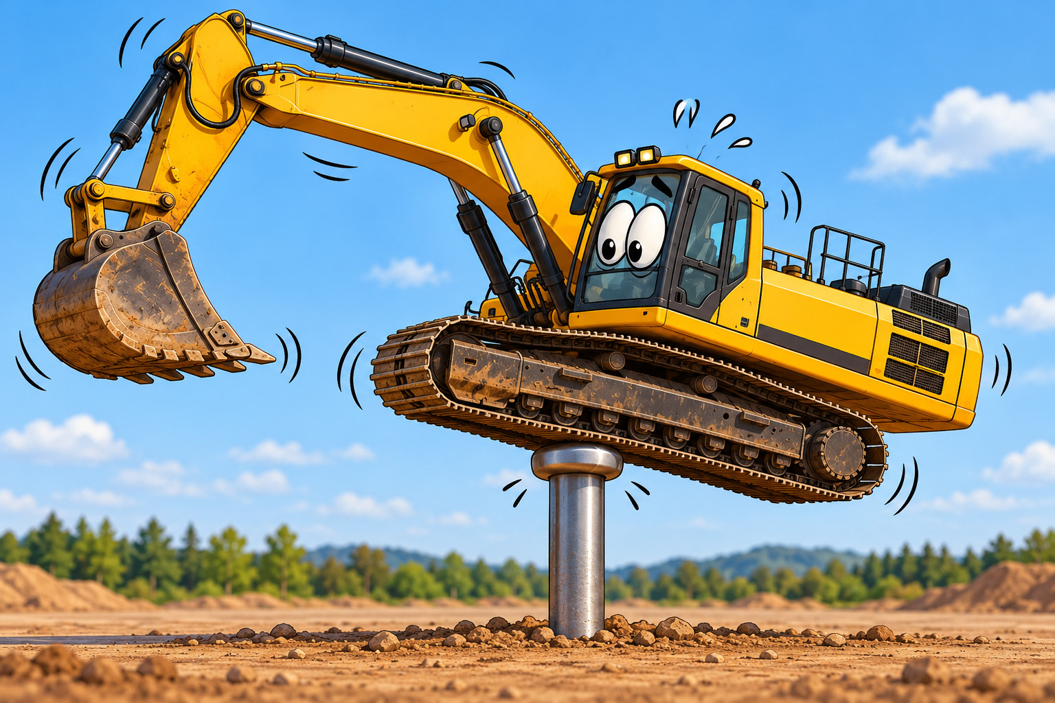
Imagine balancing an entire excavator on a single point. In theory, if that point were directly beneath its centre of gravity and the machine were properly oriented, it could remain balanced.
Of course, nobody is balancing a 40-tonne excavator on a giant pin, but the principle helps explain why the centre of gravity matters.
The location of that point depends on how the machine's weight is distributed.
An excavator's engine, hydraulic pumps, undercarriage, boom, stick, bucket, counterweight, and even the fuel in its tank all contribute to its overall centre of gravity.
And here's something important: A machine's centre of gravity isn't necessarily fixed.
On equipment with moving components, the centre of gravity changes as those components move. Extend an excavator's boom and stick, raise a wheel loader's bucket, or rotate a crane's upper structure, and the distribution of weight changes.
Engineers must account for these changes rather than designing around a single operating position.
Engineers Don't Just Find the Centre of Gravity. They Design for It.
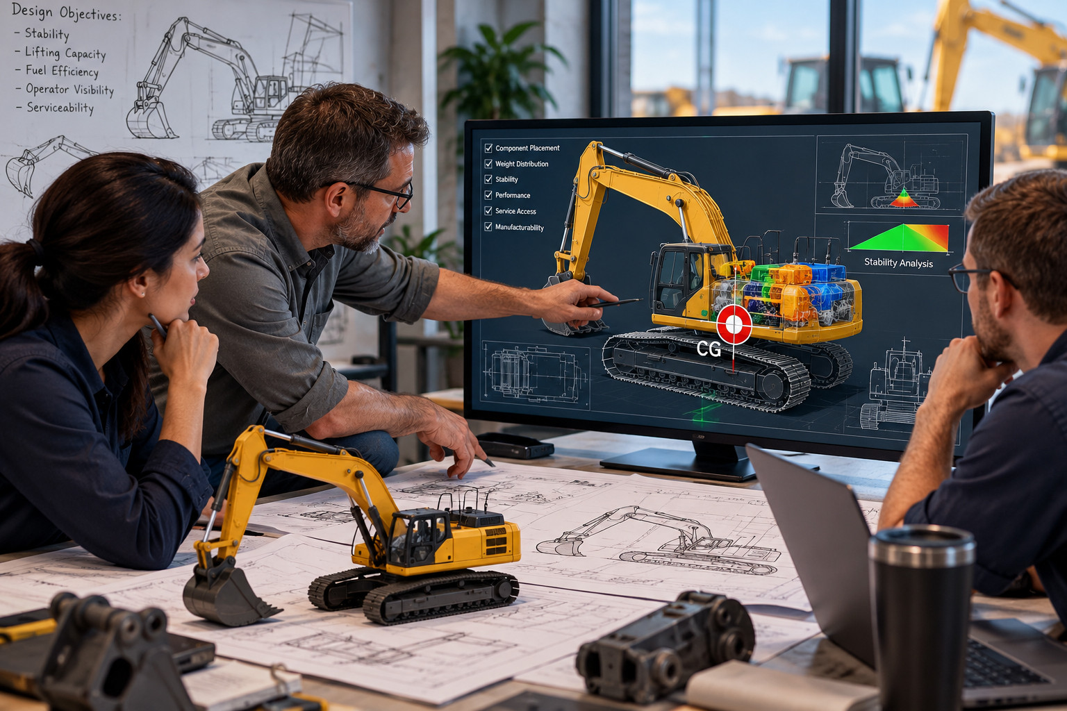
When engineers begin designing a new machine, they establish performance requirements that help determine an acceptable range for its centre of gravity.
They consider questions such as:
• How steep a slope must the machine safely negotiate?
• How much weight will it need to lift?
• How far can its attachment extend?
• Will it travel over uneven or soft ground?
• How much traction will its wheels or tracks require?
• How will the machine behave during braking, turning, and acceleration?
• What happens when the machine is carrying its maximum rated load?
These requirements influence where major components are placed.
For example, positioning a heavy engine lower in a machine can help reduce the height of its centre of gravity. Locating a counterweight farther from a tipping axis can increase its stabilizing effect.
However, engineers cannot simply put every heavy component at the bottom of the machine.
Engines need cooling airflow. Hydraulic systems need room for plumbing and maintenance. Operators need visibility. Structural components must withstand enormous forces.
The challenge is finding a practical arrangement that satisfies all these requirements without compromising stability or performance.
Why a Lower Centre of Gravity Is Usually Better
Generally speaking, a lower centre of gravity improves a machine's resistance to tipping, particularly on slopes or during turning.
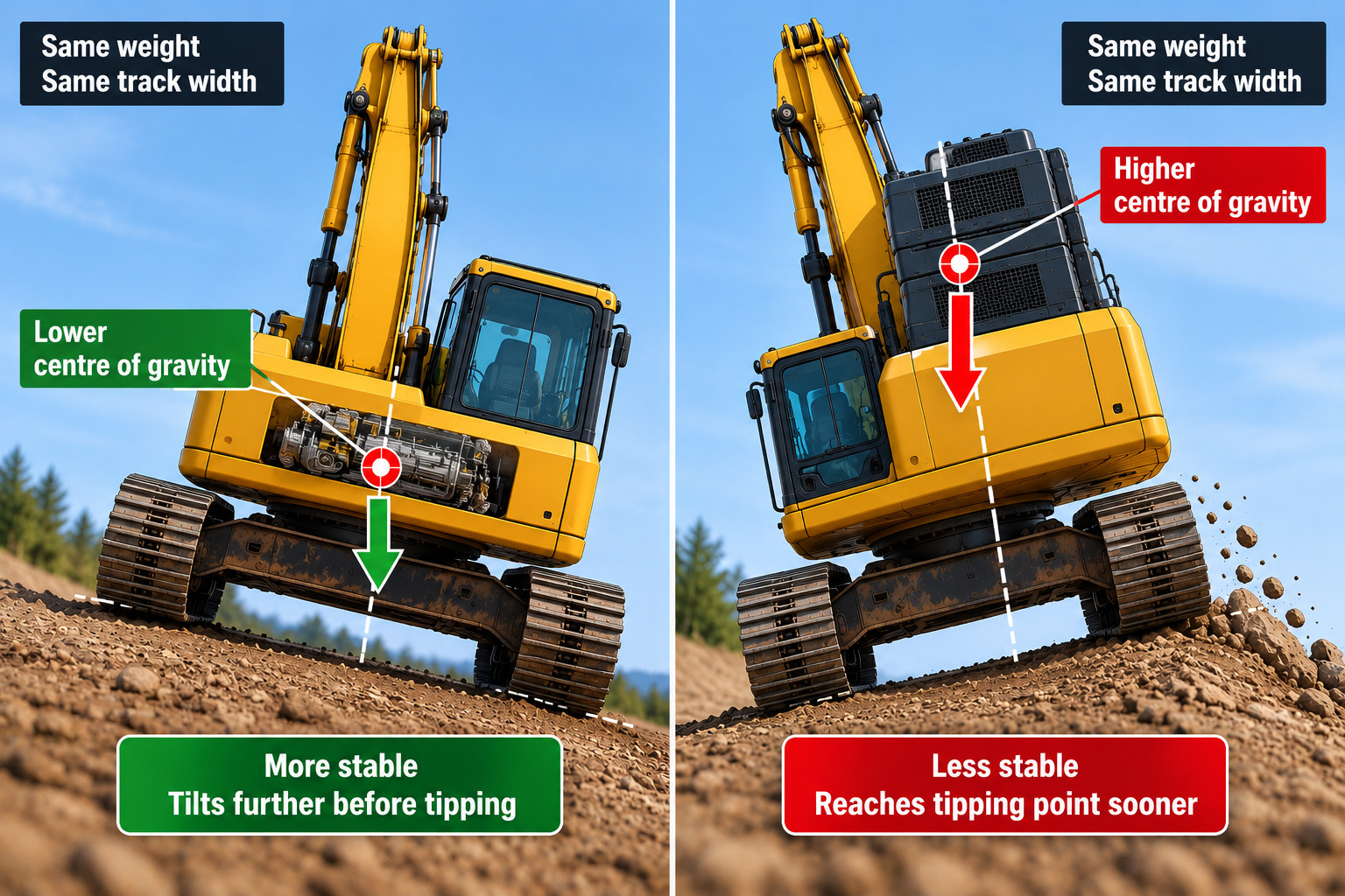
Think about two machines with identical weights and track widths.
One has most of its weight concentrated close to the ground. The other carries a significant amount of weight high above its undercarriage.
When both machines begin tilting sideways, the machine with the higher centre of gravity will generally reach its tipping threshold sooner.
This is because stability depends on the relationship between the centre of gravity and the machine's support base.
The support base is the area defined by the machine's ground contact points or contact regions. For a stationary machine on level ground, it might be approximated by the footprint of its tracks or the polygon formed by its tire contact patches.
As long as the vertical line through the combined centre of gravity remains inside that support base, the machine can remain statically stable against overturning.
When that line moves beyond the support boundary, the machine can begin to tip.
But there's an important distinction: A low centre of gravity doesn't automatically make a machine stable under every condition. Ground conditions, attachment forces, momentum, and the dimensions of its support base also matter.
The Excavator: A Constantly Moving Balancing Act
An excavator provides one of the best examples of how engineers manage changing weight distribution.
Consider the major components of a conventional hydraulic excavator:
The undercarriage provides the machine's foundation and ground contact. The upper structure contains the engine, hydraulic systems, operator cab, and counterweight. The boom, stick, and bucket extend outward from the upper structure.
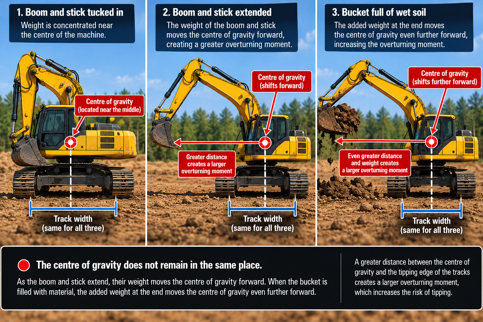
When the boom and stick are tucked close to the machine, their weight is concentrated relatively near the excavator's centre.
Extend them outward, and their combined weight produces a greater overturning moment.
Add a bucket full of wet soil, and that moment increases further.
The relationship can be expressed with a simple equation:
\[ \text{Moment}=\text{Force}\times\text{Distance} \]
In this case, distance refers to the perpendicular distance from the relevant tipping axis to the force's line of action.
A load doesn't have to become heavier to create a greater tipping risk. It can simply move farther away.
Why Not Just Install a Bigger Counterweight?
It might seem logical to solve every excavator stability problem by adding more weight to the rear.
But counterweights introduce their own engineering compromises.
A larger counterweight can improve stability in certain lifting positions, but it also increases the machine's overall mass.
That additional mass may affect fuel consumption, transport requirements, ground pressure, and component loading.
It can also create problems when the excavator is working in confined spaces, particularly if the counterweight requires a larger tail swing radius.
Engineers therefore determine counterweight size and placement according to the machine's intended operating range, structure, hydraulic capability, and stability requirements.
An excavator is not necessarily designed to remain stable while lifting any load its hydraulics can physically raise.
That's one reason excavator lift charts specify different lifting capacities depending on reach, height, and lifting direction. In some positions, stability is the limiting factor; in others, hydraulic or structural capability determines the limit.
Bulldozers: Stability Isn't the Only Goal
Bulldozers present a different engineering challenge.
Unlike an excavator, which frequently extends loads away from its body, a bulldozer primarily transfers enormous pushing forces through its blade and into the ground.
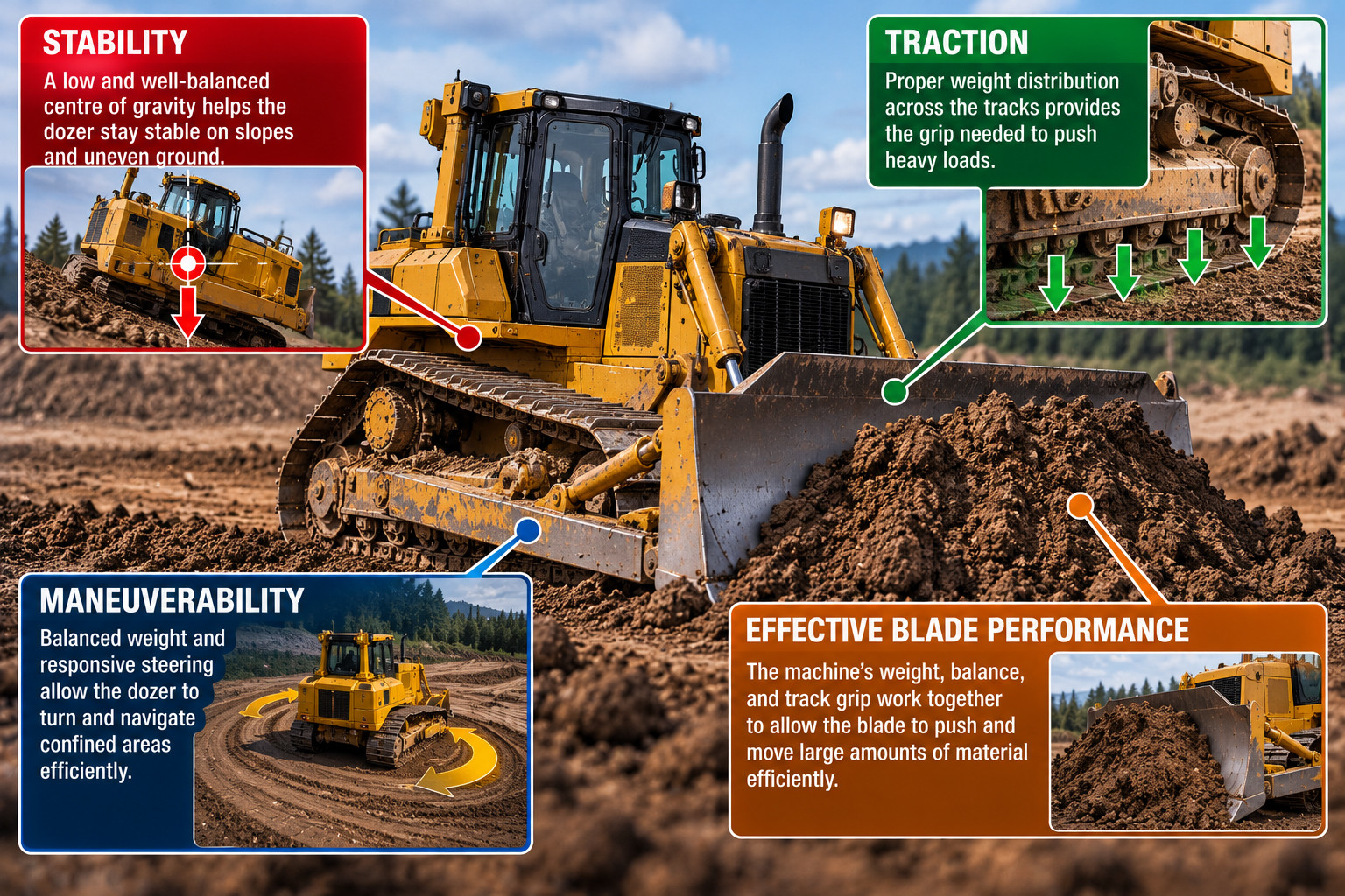
Its centre of gravity affects stability, but weight distribution also influences traction.
A crawler dozer needs sufficient weight distributed across its tracks to develop useful tractive effort.
If too much weight is concentrated toward one end, the resulting ground pressure distribution can affect how the tracks interact with the surface.
Blade position, ripper configuration, and operating forces can also shift the effective loading of the undercarriage.
For engineers, the objective isn't simply to place the centre of gravity as low as possible. It's to achieve a weight distribution that supports the machine's intended work.
A bulldozer must be stable enough for its operating conditions while maintaining traction, maneuverability, and effective blade performance.
That's a different balancing act from designing an excavator.
Wheel Loaders: What Happens When the Bucket Goes Up?
Wheel loaders demonstrate why the height of the centre of gravity can be particularly important.
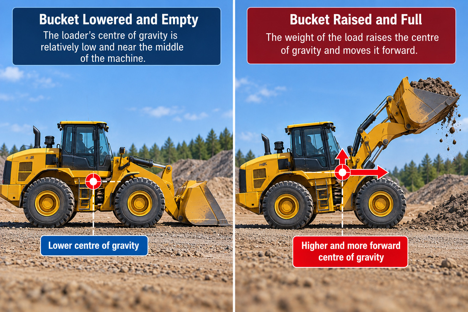
With the bucket lowered and empty, the loader's centre of gravity is relatively low.
Raise the bucket and fill it with heavy material, and the combined centre of gravity of the loader and its load generally moves upward and toward the front.That changes the machine's stability characteristics.
The situation becomes more complicated because many wheel loaders use articulated steering.
Instead of turning only their wheels, these machines steer by pivoting their front and rear frames relative to one another.
As the loader articulates, the geometry of its support base changes.
Combine articulation with a raised bucket, uneven ground, or a sudden turn, and the loader can become considerably less stable than it was while traveling straight with its bucket lowered.
This is one reason manufacturers instruct operators to carry loads low during travel.
Engineers must consider the loader's centre of gravity throughout its range of bucket positions, steering angles, and operating conditions.
Component Placement: Every Kilogram Matters
During the design process, engineers create detailed computer models that account for the weight and position of individual components.
These models allow them to estimate the machine's overall centre of gravity before a physical prototype exists.
The calculations use a weighted average of the component locations.
For one direction, the basic equation is:
\[ x_{CG}=\frac{\sum m_i x_i}{\sum m_i} \]
Here, \(m_i\) represents the mass of each component, while \(x_i\) represents its position along the chosen axis.
Similar calculations determine the centre of gravity in the other two directions.
Consider a simplified example.
Suppose engineers are designing a machine containing three major components:
| Component | Mass | Position from reference |
| Engine | 1,000 kg | 1 m |
| Hydraulic assembly | 500 kg | 2 m |
|
Counterweight |
1,500 kg |
3 m |
The combined centre of gravity along that axis would be:
\[ x_{CG}=\frac{(1000\times1)+(500\times2)+(1500\times3)}{3000} \]
\[ x_{CG}=2.17\text{ m} \]
The centre of gravity is approximately 2.17 metres from the reference point.
Now imagine moving the counterweight half a metre farther away.
Without changing the machine's total weight, the engineers have shifted its centre of gravity.
That relatively simple change can affect stability, axle or track loading, and the machine's overall balance.
Real machines contain thousands of components, of course, and engineers must consider all three dimensions. Modern computer-aided design software makes it possible to evaluate these relationships as the design evolves.
What About Fuel Tanks and Other Changing Loads?
An interesting complication is that not everything inside a machine maintains the same weight.
Fuel is consumed throughout the working day.
Hydraulic oil levels can change within reservoirs as cylinders extend and retract. Attachments may be exchanged, and buckets may carry widely varying amounts of material.
Even an operator's weight contributes to the overall calculation.
On a large mining truck, the weight and position of the payload can have an enormous influence on the combined centre of gravity.
Engineers therefore evaluate multiple loading conditions rather than assuming the machine always weighs the same amount.
They may calculate stability with full and nearly empty fuel tanks, different attachments, maximum rated payloads, and varying equipment configurations.
This helps identify operating conditions that could produce unfavorable weight distribution.
Can Engineers Predict When a Machine Will Tip?
Engineers can calculate theoretical tipping thresholds for specified conditions.
For a machine on a slope, they can evaluate how the gravitational force acts relative to the support base.
They can also model forces created by acceleration, braking, turning, lifting, and attachment operation.
However, real-world conditions introduce complications.
A tire can compress. A track can sink into soft soil. A machine can encounter a hidden depression, or a moving load can generate additional forces.
These factors may change the effective support geometry or create overturning moments that aren't present in a simple static calculation.
Consequently, engineers use more than basic centre-of-gravity calculations.
